Author Topic: 3D modeling and printing thread (image heavy)  (Read 2578 times)

Bedwyr

  • A Sticky Wicket
  • Global Moderator
  • Lieutenant Colonel
  • *
  • Posts: 10195
  • RIP. Again. And again. And again.
3D modeling and printing thread (image heavy)
« on: 02 April 2018, 14:23:16 »
This is mostly addressed to greatsarcasmo, but I want to open a general thread in case anyone else knows or is interested in the subject.

I'm new to 3D CAD design (as an electrical dude, I've mostly worked in 2D PCB design or 2D ANSYS RF sim) with a little bit of 3D modeling way back in the day. Getting spun up on Fusion 360 and expect to have ongoing questions.

My primary resource will be Fusion tutorials (https://www.autodesk.com/products/fusion-360/get-started) and Adafruit's Layer by Layer series (https://www.youtube.com/playlist?list=PLjF7R1fz_OOVsMp6nKnpjsXSQ45nxfORb).


Ok, first question. I commonly try to ask questions about edge cases to probe and better understand common best practices and find new techniques to accomplish what I want. Therefore:

- I've made a sketch from the tutorial composed of a constrained polygon and a couple circles.

- A following tutorial displays a single sketched shape using the Offset function to cut out a hole in the middle.

- It appears to be impossible to do with with the sketch composed of multiple polygons and shapes as you can only offset one shape at a time.

- But is it? Is there a way that I can make a connected copy of the composited shapes in one sketch (so that edits still affect the second sketch) and be able to use Offset to create a cutout?

- Is there a better practice to create cutouts generally?


edit: I'm changing the title now that I have a lot of medium-to-large images in here.
« Last Edit: 17 April 2018, 14:48:17 by Bedwyr »
Alas poor Photobucket. I knew him Horatio, a fellow of infinite jest, of most excellent fancy.

Bedwyr

  • A Sticky Wicket
  • Global Moderator
  • Lieutenant Colonel
  • *
  • Posts: 10195
  • RIP. Again. And again. And again.
Re: 3D modeling and printing thread
« Reply #1 on: 02 April 2018, 14:24:13 »
Feel free to add other questions for 3D printing and other modeling software packages if you're interested in the subject. I want to make this a bit more of an open subject.
Alas poor Photobucket. I knew him Horatio, a fellow of infinite jest, of most excellent fancy.

NeonKnight

  • Freelance Writer
  • Major
  • *
  • Posts: 6351
  • Cause Them My Initials!
Re: 3D modeling and printing thread
« Reply #2 on: 02 April 2018, 14:55:32 »
Tagging as I too am starting down this road...have a 3d printer, and want to start modelling.
AGENT #575, Vancouver Canada

Bedwyr

  • A Sticky Wicket
  • Global Moderator
  • Lieutenant Colonel
  • *
  • Posts: 10195
  • RIP. Again. And again. And again.
Re: 3D modeling and printing thread
« Reply #3 on: 13 April 2018, 17:28:10 »
Alright, I've done some experimenting and learned a few things. First I want to illustrate why what I was trying to do was not going to work. If you try to quote my post or any images in it, apologies for the huge hash in the web address. It was just easiest to upload to Google Photos.

Anyhow, I was trying to figure out why I couldn't hollow out a 3D sketch I made in Fusion 360. Turns out it's most likely because of particular ways the program handles 3D information as it inherits from 2D information. This may be common to other CAD programs like Autodesk or Solidworks but I'm not familiar with those so I can't comment (like I said, I'm mostly an Eagle PCB person for CAD work).

Here is the initial practice shape I made. It has parallel, horizontal, and orthogonal constraints that govern its shape and dimensions that establish the lengths (bottom edges), sides, and angle (135 degrees). Pretty simple shape that's used in the Autocad tutorial:


Next, I created two center-defined circles at the sides:


Then, I used press-pull to extrude the sketch:


The resulting 3D object looks like this:


Now what I wanted to do was go back to the original sketch and "offset" inward so that I would get a hollowed out shape. You cannot do this. The problem is that offset only works on one face at a time and those circles I added are additional faces. The reason you *can* extrude all three is because they are faces contained in the same sketch. What I think happens is that Fusion's 3D functions treat the sketch as a contained whole, enabling operations on everything within the sketch. But when you're editing inside the sketch, these are separate entities and the offset function only works one face at a time.
Alas poor Photobucket. I knew him Horatio, a fellow of infinite jest, of most excellent fancy.

Bedwyr

  • A Sticky Wicket
  • Global Moderator
  • Lieutenant Colonel
  • *
  • Posts: 10195
  • RIP. Again. And again. And again.
Re: 3D modeling and printing thread
« Reply #4 on: 13 April 2018, 17:38:16 »
So the correct way of doing this is to use arcs, not circles. This way you get a single face that can be offset.

So I deleted the circles and the two sides of the shape and started a 3-point arc:


And completed the arc tangent to the shape's horizontal lines:


What this does is create a single face in the sketch:


On which the offset function can work:

Alas poor Photobucket. I knew him Horatio, a fellow of infinite jest, of most excellent fancy.

Bedwyr

  • A Sticky Wicket
  • Global Moderator
  • Lieutenant Colonel
  • *
  • Posts: 10195
  • RIP. Again. And again. And again.
Re: 3D modeling and printing thread
« Reply #5 on: 13 April 2018, 17:45:28 »
Thus:


And I finally have a properly hollowed out object on which I can work. So adding some filleting and you get a shape like this:

Alas poor Photobucket. I knew him Horatio, a fellow of infinite jest, of most excellent fancy.

Bedwyr

  • A Sticky Wicket
  • Global Moderator
  • Lieutenant Colonel
  • *
  • Posts: 10195
  • RIP. Again. And again. And again.
Re: 3D modeling and printing thread
« Reply #6 on: 13 April 2018, 17:48:51 »
One quick addendum. Another thing I learned is to be careful of coincidence. If you make your geometry in a sketch coincident with an element in your design like the graph origin or axes, it'll link your sketch to that element and you won't be able to move it. For instance the red dot here:


Along with the clear symbol below-and-left indicates that the sketch is coincident to the origin. They're "glued" together. You have to right click that point and delete the coincident before you can move the sketch to another position on the graph. I learned this the hard way.
« Last Edit: 13 April 2018, 17:50:59 by Bedwyr »
Alas poor Photobucket. I knew him Horatio, a fellow of infinite jest, of most excellent fancy.

Bedwyr

  • A Sticky Wicket
  • Global Moderator
  • Lieutenant Colonel
  • *
  • Posts: 10195
  • RIP. Again. And again. And again.
Re: 3D modeling and printing thread
« Reply #7 on: 13 April 2018, 17:49:59 »
Hopefully this is helpful to people encountering their first true CAD package just as I am. I'll update as I learn more, such as screw threading, holes, and tap holes.
Alas poor Photobucket. I knew him Horatio, a fellow of infinite jest, of most excellent fancy.

Bedwyr

  • A Sticky Wicket
  • Global Moderator
  • Lieutenant Colonel
  • *
  • Posts: 10195
  • RIP. Again. And again. And again.
Re: 3D modeling and printing thread
« Reply #8 on: 14 April 2018, 11:49:24 »
Ok, turns out screws and threading are easy-peasy. If you're handy (insert Red-Green reference for Canadians and norther midwest peeps), it's pretty easy to suss out. I'll put a quick demo in this post, though, just to make things quicker.

The project I'll be undertaking will involve deeply sunk screw-holes so I need to figure out how to create a hole with two dimensions and proper threading in the deepest hole. Fusion 360 just does this.

To start, I create a hole and select "counterbore":


Then I move the hole to the location I want (center of the arc in that pseudo-crank I made earlier) and edit the dimensions of the hole:


I'm giving an extra 3mm of shelf in the counterbore segment and relying on ANSI standard screw sizes for a 6-32 screw (same you use to lock your hard disk down in your computer), or about 3.5mm. I extend the length of the hole past the width of the crank because I don't care about how the tap stops. Otherwise I would edit the tip angle to be either flat (the screw won't reach that far) or an appropriate angle for the screw type if it has a sharp tip.

Note: You don't have to make the hole dimensions match the screw standards precisely as it'll "pop" to match the threading size you assign. I'm just keeping it close so I know what I'm looking at and can judge the counterbore size better.

There is a specific option (yay! I've only used 3D modeling programs before so its nice to see CAD packages make stuff like this easy) for threading in the create menu. I select the deeper section of the hole and apply the thread. There is a specific option for 6-32 screws (#6):


You can find most sizes in the dropdown including standard metric sizes (M3, M4, etc).

The final hole looks like this:

Alas poor Photobucket. I knew him Horatio, a fellow of infinite jest, of most excellent fancy.

Bedwyr

  • A Sticky Wicket
  • Global Moderator
  • Lieutenant Colonel
  • *
  • Posts: 10195
  • RIP. Again. And again. And again.
Re: 3D modeling and printing thread
« Reply #9 on: 15 April 2018, 01:25:33 »
I'm starting to work on a project now that involves the Raspberry Pi. I have the dimensions in front of me and I'm sketching out some of the 2D dimensions to provide a point space from which to work the 3D geometry. No pictures for this one, but I want to share a quirk of the software.

You cannot arbitrarily move a sketch component to a global coordinate. To do this you need to make relative dimensions to a point from the origin. It's a bit backward from the "normal" way one does this in something like Blender or Eagle. The linked video illustrates how to do this:

https://knowledge.autodesk.com/support/fusion-360/getting-started/caas/screencast/Main/Details/df7db85f-fe48-460e-b79a-844b46fc422c.html
Alas poor Photobucket. I knew him Horatio, a fellow of infinite jest, of most excellent fancy.

Bedwyr

  • A Sticky Wicket
  • Global Moderator
  • Lieutenant Colonel
  • *
  • Posts: 10195
  • RIP. Again. And again. And again.
Re: 3D modeling and printing thread
« Reply #10 on: 15 April 2018, 13:07:02 »
Update.

I think I'm understanding a bit more about F360 workflows. Sketches do more than provide bases from which you can extrude  3D objects. They also provide constraints inside which you can more easily model your 3D object. Think of it like making the plan and profile views ahead of time and then making the 3D geometry afterwards, snapping your elements to those 2D sketches.

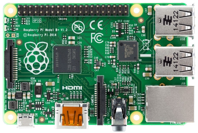
Right now I'm editing the imported DXF sketch of the Raspberry Pi from raspberrypi.org. They only have a DXF file for the Raspberry Pi 3B so I'm editing the imported sketch so that it aligns with the features of the new Raspberry Pi 3B+.

What I've realized in the process of doing this is that Fusion 360 (and likely AutoCad and similar packages) is that they are *not* oriented toward global coordinates at all. Apparently, if you're thinking this way--which is very understandable coming from other kinds of design software--you're doing it wrong. Everything is relative to the existing sketch elements. This makes sense if you think about how common industrial drawings work. I'm used to dealing with a more flexible hybrid approach, sometimes it's appropraite to use global coordinates, sometimes relative depending on what you're doing.

Anyhow, this means that I should be using and adjusting with dimensions. Lots and lots of dimensions, thinking about where a part was and is going to go relative to the board. For example, the picture below shows the new power-over-etherned header on the Raspberry Pi B+. I had to copy the old PEN-RUN header, move that down, and expand the PoE header to accommodate four pins. From the RPI mechanical drawing, I inferred that all the elements needed to be adjusted up 0.377mm and two holes added below. The mechanical drawing only shows the bounding box for the header and not strict pin locations, so I'll try to double-check with a caliper.

Alas poor Photobucket. I knew him Horatio, a fellow of infinite jest, of most excellent fancy.

Bedwyr

  • A Sticky Wicket
  • Global Moderator
  • Lieutenant Colonel
  • *
  • Posts: 10195
  • RIP. Again. And again. And again.
Re: 3D modeling and printing thread
« Reply #11 on: 17 April 2018, 10:36:00 »
I've now learned some more. The big lesson this time is that the way bodies and components are handled in Fusion 360 are a lot more important than I thought.

I'm used to a 3D entity being explicitly a 3D entity. You can group them into containers that allow new ways for them to be manipulated, but the containers were explicitly a grouping and group properties mechanism.

This is not true here.

In 360--and I presume Solidworks and Autocad most likely--there is a physical object container and the 3D modeling object itself. The modeling object is purely for mucking around with geometry till it looks right or has the right dimensions. That's a body. If I want to make it act like a single physical object, then I need to put all the geometry that will operate as the physical object into a single container. That container is the component. Moving components around is a lot easier than moving bodies around and I think that this organizing framework makes a lot more sense in context.

Anyhow, components get connections between them called joints which can be rigid or moving (like hinged, rotating, etc). And you can group components into a new component that is called a subassembly. I haven't gotten far enough to understand the ins and outs of when to define a subassembly but likely it depends on the design you're trying to create.

A few illustrations to demonstrate this and something else I learned.


You can see below these objects that I applied a decal to the Raspberry Pi substrate shape. I'm recreating the dimensions of the GPIO header so that when I design an enclosure I have good clearance. Especially if I need to plug something directly into the header. If you look carefully you can see the blue outlines from the sketch I was working on below. The pins show at each base an icon of interlocking  teeth indicating that I rigidly joined the pins to the spacer at a point. Each pin and the spacer are now components containing bodies and I joined the components together. Ultimately I will group these into a subassembly I'll call "Header 1" (because there are two important pin headers on the Raspberry Pi 3B+).

How did I figure out where to join the pins? I projected the circle centers from the sketch onto the top face of the spacer (those magenta circles in the images above and below). It's an option in the sketch menu I hadn't considered before:


See, I was thinking project' as in 'task'. Not  'project' as in 'projection'. Anyhow, using that tool I can get points, shapes, and centroids from the sketch onto 3D geometry so that I can use them to do things like joints.

One thing at the back of my mind that I'm not yet sure about is whether there's any issue with the location of the joint when I copy the design out for use in another design. Probably not, but we shall see.
« Last Edit: 17 April 2018, 10:37:34 by Bedwyr »
Alas poor Photobucket. I knew him Horatio, a fellow of infinite jest, of most excellent fancy.

Bedwyr

  • A Sticky Wicket
  • Global Moderator
  • Lieutenant Colonel
  • *
  • Posts: 10195
  • RIP. Again. And again. And again.
Re: 3D modeling and printing thread
« Reply #12 on: 17 April 2018, 10:44:07 »
By the way all, this is kind of turning into a learning blog but I definitely still welcome questions, comments, input, and other product learning and experiences. I'm sure there are CAD design pros cringing at my poor attempts so far. Chime in.

Fusion 360 is a very powerful modeling CAD package that's geared partially toward 3D printing and design, not just professional CAD workflows. 360 is freely available to anyone who wants to use it.
Alas poor Photobucket. I knew him Horatio, a fellow of infinite jest, of most excellent fancy.

Bedwyr

  • A Sticky Wicket
  • Global Moderator
  • Lieutenant Colonel
  • *
  • Posts: 10195
  • RIP. Again. And again. And again.
Re: 3D modeling and printing thread
« Reply #13 on: 17 April 2018, 14:47:37 »
Ok, another update reflecting increased understanding of F360's workflow.


So I was working on the RPI's 40 pin header and trying to get the components from the previous posts into a subassembly. The workflow of Fusion 360 is a bit different, apparently. There is no "subassembly" or "assembly" container within the design. The program is intended for people to work on assemblies in separate designs. So what I did is select the components of the header and did a "save as" into a separate design file.

Then I deleted those same components from the Raspberry Pi as I want the assembly for the header included from the outside design. Then I selected the RPI header from the browser on the left side and selected "insert into current design":


Sorry for the large size, but I could only shrink so far before losing text and the context of this action is important.

What you're seeing here is my homemade Raspberry Pi 3D reference. The blue enclosure box in the project browser on the left is someone elses I'm using as a reference to make my own, partly to learn Fusion and partly to have a dimension guide that's less load on the computer (they included every surface mount element including resistors and capacitors... which was absurd, IMO).

What the insertion does is place that assembly back into my RPI design and, more importantly, acts as an independent assembly that will update for all other designs I place it into. So for example, if I later decide I want a higher fidelity representation of the header like this:


where the standoff plastic is lumped so you can snip and break off sections, I can do that in the header assembly design and have it automatically update in all the designs into which I've inserted it.

For now that's not necessary. I'm not making mechanical models for production. I'm just trying to get a height reference and, if necessary, a pin reference for plugs.

When I do this, the RPI design looks like this:


That link on the left indicates that the assembly depends on an external design and I can't edit it directly inside this design. If I decide later that that's actually stupid and I don't want a separate file, I can break the link in a right-click option and just have it exist solely in this design.

Why I can't just make an assembly as-is within the design is unknown to me, but I can see what Autodesk is going for in a shared, distributed workflow.
« Last Edit: 17 April 2018, 14:49:57 by Bedwyr »
Alas poor Photobucket. I knew him Horatio, a fellow of infinite jest, of most excellent fancy.

IAMCLANWOLF

  • Freelance Artist
  • Major
  • *
  • Posts: 3537
Re: 3D modeling and printing thread
« Reply #14 on: 17 April 2018, 16:34:31 »
360 is freely available to anyone who wants to use it.

Is it? I thought it was only free to students/academia? Which is why I've been learning OhShape.

I'd prefer to use Fusion though, as AutoCAD is my lifeblood. I'm hoping some of the fast commands are shared.   

Bedwyr

  • A Sticky Wicket
  • Global Moderator
  • Lieutenant Colonel
  • *
  • Posts: 10195
  • RIP. Again. And again. And again.
Re: 3D modeling and printing thread (image heavy)
« Reply #15 on: 17 April 2018, 16:43:00 »
https://www.autodesk.com/products/fusion-360/free-trial

Follow the instructions there for "Are you a startup or hobbyist? You may qualify for free use."

This way I get a year's trial renewable indefinitely. They don't assert that they'll continue the free license forever, but a post by one of the VPs said that they regard this as a great success for getting people to ultimately buy licenses for the product and they don't intend to change the practice.
« Last Edit: 17 April 2018, 17:06:26 by Bedwyr »
Alas poor Photobucket. I knew him Horatio, a fellow of infinite jest, of most excellent fancy.

IAMCLANWOLF

  • Freelance Artist
  • Major
  • *
  • Posts: 3537
Re: 3D modeling and printing thread (image heavy)
« Reply #16 on: 17 April 2018, 17:58:53 »
Oh, nice! Thank you.

Bedwyr

  • A Sticky Wicket
  • Global Moderator
  • Lieutenant Colonel
  • *
  • Posts: 10195
  • RIP. Again. And again. And again.
Re: 3D modeling and printing thread (image heavy)
« Reply #17 on: 17 April 2018, 18:06:03 »
Why don't you go for a license and we can leverage your CAD knowledge to figure out this software?
Alas poor Photobucket. I knew him Horatio, a fellow of infinite jest, of most excellent fancy.

IAMCLANWOLF

  • Freelance Artist
  • Major
  • *
  • Posts: 3537
Re: 3D modeling and printing thread (image heavy)
« Reply #18 on: 18 April 2018, 14:39:00 »
Why don't you go for a license and we can leverage your CAD knowledge to figure out this software?

I use 2D CAD for nearly everything I detail (structural steel, and piping). It's not sexy, but-- speed is everything in this segment. I'm simply learning 3D again in my spare personal time.